Suspension Component as a sample use case for AMable
This use case shows how AMable services can support all stakeholders in the uptake of additive manufacturing (AM). Functional parts with safety challenges can be constructed to overcome limitations from conventional manufacturing. Have a look inside!
Suspension Component

LMS has established a framework towards replacing conventional manufacturing processes with Additive Manufacturing for structural components [1]. This case demonstrates an effective replacement of a part (Formula Student car suspension upright), previously manufactured via milling, with a part build by AM. Formula Student is an engineering design competition where students are challenged to design and manufacture an electric formula-style racing car. The Formula Student team UoP Racing has been founded by LMS in 2001 and is part of its Teaching Factory activities.
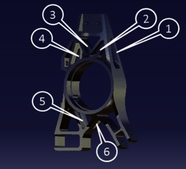
The upright is a crucial component of every car’s suspension system, due to the fact that all forces exerted to the vehicle during its operation, are transferred to the chassis through them. Their function is to provide a physical connection from the wheels to the suspension links and to provide mounting points for the installation of the brake caliper. These parts have to provide adequate strength and stiffness under various types of loads, while being lightweight in order to keep the car’s total weight as low as possible to aid their dynamic performance.

Normally, the selection of potential parts to be substituted by new designs made by AM is a decision based on empirical observations or previous knowledge and experience on the specific application. This decision is also based on specific requirements that have to be addressed and assure that the particular part can be fabricated by metal AM processes. The material used for the fabrication of these parts should also be examined in order to verify that metal AM machines can support the manufacturing of parts with the corresponding material. In a different case, other metal alloys should be considered. Additionally, the design limitations, due to the current manufacturing process utilized, are obtained. LMS assisted the selection of an appropriate part as well as AM process, material and machine, following a specific structured process that will be part of the AMable service portfolio.
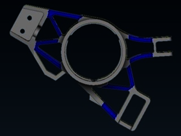
Furthermore, connecting plates or brackets manufactured for joining the components with the rest of the assembly were integrated into a singular design, thus saving weight and assembly time. The constraints imposed from the operation environment of the investigated component were respected, and re-design from scratch was not favoured for the sake of simplicity. Mounting points and dedicated areas for the installation of other mechanical parts, such as bolts, bearings, springs, shocks etc. remained the same during the re-design phase, due to the fact that the choice of these items is based on interdependent criteria and their rearrangement in the assembly may cause implications with their interface in the rest of the car.
An iterative re-design procedure using implementing topology optimization and finite element analysis (FEA) algorithms was utilized. The optimization task was the generation of a structure maintaining the component’s stiffness threshold, while enabling a volume (thus weight) reduction. The result was a new design, suitable for use in the existing operational conditions of the assembly (as imposed by the rest of the components), which is lighter while at the same time maintaining the level of stiffness that is required.
As a final step, the new design was verified in terms of performance targets; weight, structural performance (displacement, max stresses), while also addressing its operability inside the assembly. As soon as it is obtained that the new component can be effectively incorporated in the assembly, without sacrificing performance and mainly avoiding the re-design of other parts to be fitted in.
Using the established performance measures (weight and stiffness), a comparison between the new design, optimized for Additive Manufacturing, and the pre-existing one, optimized for milling, can be accomplished.
Part Description | Weight (kg) | Volume (m3) | Max Stress (MPa) | Deformation (mm) |
Initial model | 0,49 | 173,3 | 202 | 0,357 |
Optimized model | 0,39 | 138,64 | 248 | 0,37 |
Variation percentage | 20,4 % reduction | 25% reduction | 18,5 % increase | 3,6 % increase |
Table 1: Comparative table between initial and optimized part in terms of weight, volume and stiffness values
AM Process | 3-Axis CNC Milling Process |
AlSi10Mg Aluminium powder | 7075-T6 Aerospace Aluminium |
Part Volume: 138,64 e-6 m3 | Part Volume: 173,3 e-6 m3 |
Material used: 14 e-5 m3 | Material used: 28,8 e-5 m3 |
Process Time: 5,2 h (approximately) [18] | Process Time: 8,5 h (approximately) |
Mass: 0,39 kg | Mass: 0,49 kg |
Table 2: Comparison table of AM and milling production aspects for the investigated component
The results indicate that the redesign of the part was successful, achieving lower total volume and subsequently weight, while maintaining the maximum stresses and deformations at similar levels. The level of weight reduction is significant, especially when this is achieved for motorsport purposes. The potential of the car’s performance due to its reduced weight is doubled, because the particular design is implemented in both rear wheels of the car. Finally, as soon as the design iterations have been completed and the performance measures have been met, the component should be able to directly replace the pre-existing part without any further modifications required to other parts of the assembly and/or car.